8 Blades, 8’ 6” Wide
This is our most popular Trail Paver II model, the 8 Blade, 8’ 6” Wide, 24’ 6” long from the Pintle to the rear of the Pan. It pulls easier than a much lighter weight conventional “DRAGS”!
The 8 Blade is also made in 9’ 6” and 10’ 6” Wide Models. We also build 10 and 12 Blade Models, they are configured the same, but length increases with number of Blades.
Features and Benefits:
The Trail Paver II can cut and process snow at temperatures above 32 Degrees !
Heavy duty construction, use the Trail Paver II for early season trail “grading”, where conditions permit! The wheels are mounted internally for protection, ease of crossing roads, gives you a shorter turning radius and better rear visibility!
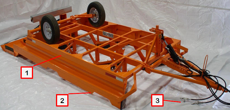
1. 22” high side panels to keep all processed snow on the trail!
2. The bottom side rail is ½” x 8” AR-400 Wear Plate, for unlimited cutting depth!
3. Hydraulic Flow Valves for the Packer Pan are standard on hose ends for easy adjustment; they control the speed of the up and down movement!
The Trail Paver II has a huge 19” high front opening, to allow unrestricted amounts of snow to be processed without plugging! Also has tree guards for front corner protection.

4. Cut (19” +) in one pass, to the bottom of the Moguls, and remove the trail memory.
5. The front blades extend below and out board of the lower ½” wide AR-400 side rails, for unlimited cutting depth.
6. All Blades & Skags are AR-400 wear plate. The blades have our modified Shark Tooth design that resists sticks and limbs from wedging in the teeth! They are concentric and reversible so they can be used in the other blade locations.

7. Non-tripping blade holders (4 x 4 x ¾ angle iron), “If your blades are tripping, they are not cutting.” No springs to break! Mounted at an angle to increase the rolling action and ride over trail obstructions.
8. All blades holders have forward angled snow roll plates, to give superior mixing, heating action.
9. Our unique blade and skag adjuster plates give infinite adjustments and lock them in place, simple and easy.
10. The straight hitch is standard (a Cushion Hitch is Optional); it has our unique height adjustment system, to work properly with any pintle height you may have! Gooseneck and Ram Steering is optional.
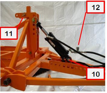
11. Anti-jack knife feature on the hitch is a unique feature which allows the Trail Paver II to “Float”, also prevents the hitch from folding up too far when the Trail Paver II is backing up! Shown here, the L bracket, is shown in the Transport Position, the 2 positions (holes to the rear) adjust the “Float”, and they limit how far the Trail Paver II hitch can fold up.
12. Hydraulic flow valves are standard, the front cylinder regulated going down, pan cylinders are regulated up & down.
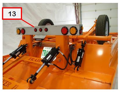
13. A stainless steel rear light-bar is standard; L.E.D. tail, stop, turn, marker, 7 mode flasher w/ yellow lights and rear flood/backup light! A 7 pronge flat RV plug at the hitch, it has DOT lights and is trail safe.
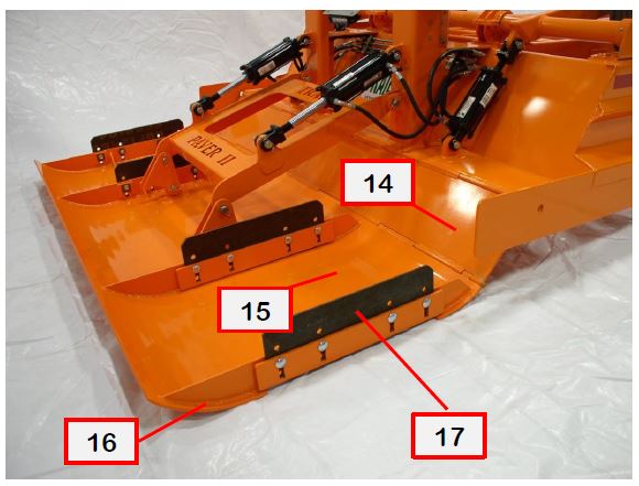
14. The Hydraulic Packer Pan has a 12” wide double hinge between it and the rear of the process section. This puts more down pressure on the Packer Pan / Trail, for added compaction! Also this gives the Trail Paver II the capability to do many things conventional “Drags” cannot do.
15. It allows the operator to control the amount of snow carried in the process section.
16. You can Back a Trail Paver II anywhere on the trail and not leave a mound of snow (trail hazard!).
17. The 5/16” thick skags are AR-400 wear plate; they are infinitely adjustable and locked in place by our unique blade/skag adjuster plates.
An Industry First Since 2012
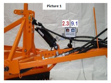
All Trail Paver II’s have Digital Hydraulic Cylinder Position Indicators, it is a wireless system between the Node Transceiver (in a waterproof enclosure) in the rear light bar and a Gateway Transceiver in the Digital Hydraulic Cylinder Position Indicator in the Cab, as shown in the following 4 pictures. The Indicator gets the signals from sensors inside the cylinders, and both are wired to the rear Node Transceiver, through the steel frame of the Trail Paver II for protection. The is Digital Display is supplied with a HD suction cup mount, so it can be located on the windshield for easy viewing by the operator, it has a 4’ long 12 VDC cord and a fused cigarette lighter plug.
You can switch the Trail Paver II and Digital Display from one pulling unit to another as long as the Pulling unit can supply power to the RED WIRE in the Rear Lightbar, it powers the Node Transceiver. When powered and operating properly, the Node will have a Green flashing LED in the window of the Lightbar! The Digital Display is bound to that TP Node and no other, put Digital Display in the Cab and plug it in to 12 VDC, it’s that simple.
This is great system for your operators, to know the Cutting Depth and the Height of the Rear Leveling Screed by controlling the Packer Pan pressure on the trail surface. Also for units with limited rear visibility, stormy, windy or low rear visibility conditions, a great aid to training new operators to eliminate the trail memory!
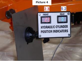
What the Hydraulic Cylinder Digital Position Indicators shows the operator, is a “number” that equals “a cylinder position” that is always repeatable!
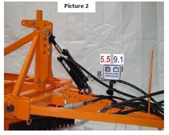
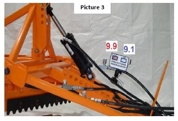
The digits in the (RED) display, indicates the position change of the Front Cylinder. As the numbers increase the cylinder is extending, the cylinder is raising the Front of the Trail Paver II. You should cut deep enough in (1) pass to remove the Trail Memory, no more!
The (BLUE) display is indicating the position of the Packer Pan Cylinders, as it raises or lowers the rear of the process section, this controls the amount of snow being carried in the rear of the process section. This also increases the packing pressure put on the trail. Adjust the Packer Pan in small increments (1 digit at a time), until the Trail Paver II is only carrying 18” to 24” of snow in front of the Rear Baffle! All snow should now be moving freely to the rear.